Solar String Sizing Calculator for India: Cold Voc, Hot Vmp and Modules per String
Free solar string sizing calculator for Indian conditions. Enter module and inverter datasheet values to find the safe range of modules per string — checked against cold-morning Voc, hot-afternoon Vmp and inverter current limits — with the method explained.
Getting the number of modules per string right is one of the most important decisions in a solar design. Too many modules and the string can exceed the inverter's maximum DC voltage on a cold, bright morning — tripping on PV overvoltage or even damaging the inverter. Too few and the voltage can fall below the inverter's MPPT range on a hot afternoon, costing generation exactly when the sun is strongest.
This free calculator checks both limits, plus the inverter's input current, using values straight from your module and inverter datasheets. It runs entirely in your browser — nothing is sent anywhere.
How to use the calculator
- Enter the module values from its datasheet: Voc and Vmp at STC, Isc, and the temperature coefficients. If the datasheet gives only a Pmax coefficient, it's a reasonable stand-in for the Vmp coefficient.
- Enter your site's temperature extremes. For the cold limit, use the record low ambient temperature for the site — cells can be at or slightly below ambient at dawn. For the hot limit, use a realistic peak cell temperature; 65–70 °C is common on Indian rooftops in summer.
- Enter the inverter's limits for one MPPT input: maximum DC voltage, MPPT voltage range and maximum input short-circuit current.
- Enter your design — modules per string and strings in parallel on that MPPT — and read the checks.
The defaults show a typical 540 Wp module on a 1000 V three-phase string inverter in a north Indian city.
Reading the results
The calculator shows a safe range of modules per string at the top, then six checks for the string length you entered:
- Module Voc at the coldest temperature and module Vmp at the hottest temperature are the corrected per-module values every other check is built on.
- String Voc on a cold morning must stay below the inverter's maximum DC voltage. A "Check" here is the most serious result — reduce the number of modules.
- String Vmp on a hot afternoon should stay above the MPPT minimum. A "Check" means the inverter may lose tracking or fail to start in summer — add modules or choose an inverter with a lower MPPT minimum.
- String Vmp on a cold morning should ideally stay below the MPPT maximum. A "Check" here isn't a safety issue, but the inverter may not extract full power on bright winter mornings.
- Short-circuit current for all strings on the MPPT must stay within the inverter's input limit.
If every row shows "OK", the string length works for the values you entered. It's still worth leaving a margin rather than designing to the exact limit.
The method behind the numbers
Module voltage changes with cell temperature. The datasheet values are measured at 25 °C, so we correct them:
Voc(T) = Voc(STC) × [1 + β(Voc) × (T − 25)]
Vmp(T) = Vmp(STC) × [1 + β(Vmp) × (T − 25)]
where β is the temperature coefficient as a fraction (−0.27 %/°C = −0.0027).
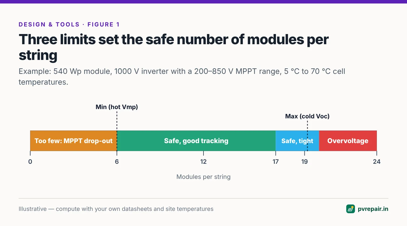
Then three limits set the safe range:
- Maximum modules per string = maximum DC voltage ÷ module Voc at the coldest temperature (rounded down). Exceeding this risks overvoltage.
- Minimum modules per string = MPPT minimum voltage ÷ module Vmp at the hottest temperature (rounded up). Below this the inverter can't track the maximum power point on hot afternoons.
- Preferred maximum for tracking = MPPT maximum ÷ module Vmp at the coldest temperature. Above this the string still works safely, but the inverter may clip voltage on cold, bright mornings.
Finally, the total short-circuit current of the strings on one MPPT should stay within the inverter's rated maximum input short-circuit current.
Worked example
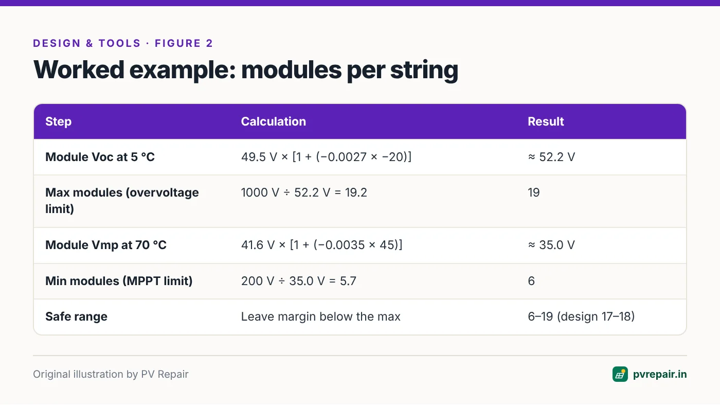
With a 49.5 V Voc module (β −0.27 %/°C), a site minimum of 5 °C and a 1000 V inverter:
- Module Voc at 5 °C = 49.5 × [1 + (−0.0027 × −20)] = 49.5 × 1.054 ≈ 52.2 V
- Maximum modules = 1000 ÷ 52.2 ≈ 19.2 → 19 modules
With a 41.6 V Vmp module (β −0.35 %/°C), a peak cell temperature of 70 °C and a 200 V MPPT minimum:
- Module Vmp at 70 °C = 41.6 × [1 + (−0.0035 × 45)] = 41.6 × 0.8425 ≈ 35.0 V
- Minimum modules = 200 ÷ 35.0 ≈ 5.7 → 6 modules
So the safe range is 6 to 19 modules. Most designers would avoid sitting right at 19 and leave a margin — 17 or 18 modules — to allow for module tolerances and unusually cold days.
Second example: a single-phase residential inverter
Residential PM Surya Ghar systems usually use single-phase string inverters with lower voltage limits. Suppose the inverter has a maximum DC voltage of 600 V and an MPPT range of 90–520 V, with the same 540 Wp module:
- Maximum modules = 600 ÷ 52.2 ≈ 11.5 → 11 modules
- Minimum modules = 90 ÷ 35.0 ≈ 2.6 → 3 modules
- Preferred maximum for tracking = 520 ÷ (41.6 × 1.07) ≈ 520 ÷ 44.5 ≈ 11.7 → 11 modules
A typical 3 kW system with six of these modules in one string sits comfortably in the middle: about 313 V on a cold morning and about 210 V on a hot afternoon. If the household later wants to expand to 10 or 11 modules, the string still fits — but a 12th module would not, so an expansion beyond that needs a second string or MPPT input.
Where to find each value on a datasheet
Module datasheets put the electrical values in a table labelled "Electrical characteristics (STC)" — look for Voc (open-circuit voltage), Vmp or Vmpp (voltage at maximum power), Isc (short-circuit current) and Imp. Temperature coefficients are usually in a separate "Temperature characteristics" table: the Voc coefficient is often written as β or TkVoc, and the Pmax coefficient as γ or TkPmax. If no Vmp coefficient is given, the Pmax coefficient is a reasonable, slightly conservative substitute.
Inverter datasheets list, per MPPT input, the maximum input voltage, the MPPT voltage range (sometimes a narrower "full-load MPPT range"), the start-up voltage, the maximum input current and the maximum short-circuit current. When a datasheet gives a full-load MPPT range, use its lower limit as the MPPT minimum if you want the inverter to deliver full power on hot afternoons.
A note on bifacial modules and current
Bifacial modules collect light on their rear side, which adds current — sometimes 5–15% or more over light-coloured roofs and elevated structures. Voltage barely changes, so the voltage checks above still apply. But when you parallel strings on one MPPT, multiply Isc by the bifacial gain you expect before comparing it with the inverter's short-circuit current limit, and leave a margin.
Indian conditions to keep in mind
- North Indian winters. Plains cities can see dawn temperatures of 2–6 °C, and hill states go below freezing. Clear winter mornings combine cold cells with bright sun — the worst case for overvoltage.
- Summer rooftops. Cell temperatures on dark roofs and low-tilt structures regularly reach 65–70 °C. Short strings on single-phase inverters with high MPPT minimums are most at risk of dropping out.
- Elevated structures run slightly cooler than flush-mounted arrays because of airflow underneath.
- Bifacial modules add current rather than voltage; check the current limit with the bifacial gain your site can produce.
- Mixed orientations (east and west) on one MPPT input should have equal string lengths.
Common string sizing mistakes
- Designing to STC Voc and ignoring temperature.
- Using average winter temperatures instead of the record low.
- Adding modules to an existing string during an expansion.
- Changing module model at procurement without rechecking string lengths.
- Forgetting the MPPT minimum on single-phase inverters with high start voltages.
- Exceeding the inverter's input current when paralleling strings with high-current modules.
When to use design software instead
A calculator is ideal for quick checks and for understanding the limits. For full designs — with shading, multiple roofs and orientations, cable sizing, SLDs and proposals — design software applies the same checks automatically for every string. See our comparison of 3D solar design software for Indian EPCs and our PM Surya Ghar design guide for the complete workflow.
Frequently Asked Questions
How many solar panels can I connect in series?
Divide the inverter's maximum DC voltage by the module's open-circuit voltage at the site's coldest temperature, and round down. Then check that the string's maximum-power voltage on hot afternoons stays above the MPPT minimum. The calculator above does both.
Which temperature should I use for the cold limit?
Use the record low ambient temperature for the site, not the average winter temperature. On clear nights, modules can cool to around ambient or slightly below.
Why does string voltage rise in winter?
Solar cell voltage increases as temperature falls — typically by about 0.25–0.30% of Voc per °C for modern crystalline modules. A string at 990 V at 25 °C can exceed 1,040 V on a 3 °C morning.
What happens if my string voltage is too low?
If the string's operating voltage falls below the inverter's MPPT minimum (common on hot afternoons with short strings), the inverter can't track maximum power and output drops — or the inverter may not start in the morning.
Does this calculator work for microinverters and optimisers?
No. Module-level power electronics change the string limits. Use the manufacturer's design tool for those systems.
Sources
- IEC 62548 (photovoltaic array design requirements) — design principles for string voltage and current — webstore.iec.ch
- PV Repair, "PV Overvoltage Error: When String Voltage Exceeds Your Inverter's Limit" — pvrepair.in
Related guides
SolarDraft Review (2026): Features, Pricing, Pros and Cons for Indian Solar EPCs
An independent review of SolarDraft, the browser-based 3D solar design, proposal and CRM software for Indian EPCs — what it does well, where it falls short, what it costs, and who should choose an alternative.
Solar Designer Review (2026): 3D Rooftop Design, DISCOM Drawings and BOM for Indian EPCs
An independent review of Solar Designer (solardesigner.in), the browser-based 3D rooftop solar designer that produces a full drawing pack, SLD and bill of materials — strengths, limitations, and who should choose an alternative.
How to Design a Rooftop Solar System Under PM Surya Ghar: A Step-by-Step Guide for Installers
A practical, step-by-step guide for installers designing residential rooftop solar under PM Surya Ghar — sizing from the electricity bill, roof area, DCR modules, string and cable design, earthing, subsidy-aware proposals and the paperwork that gets approved first time.